Building a Rocket Engine from Scratch
How I learned to stop worrying and love the burn.
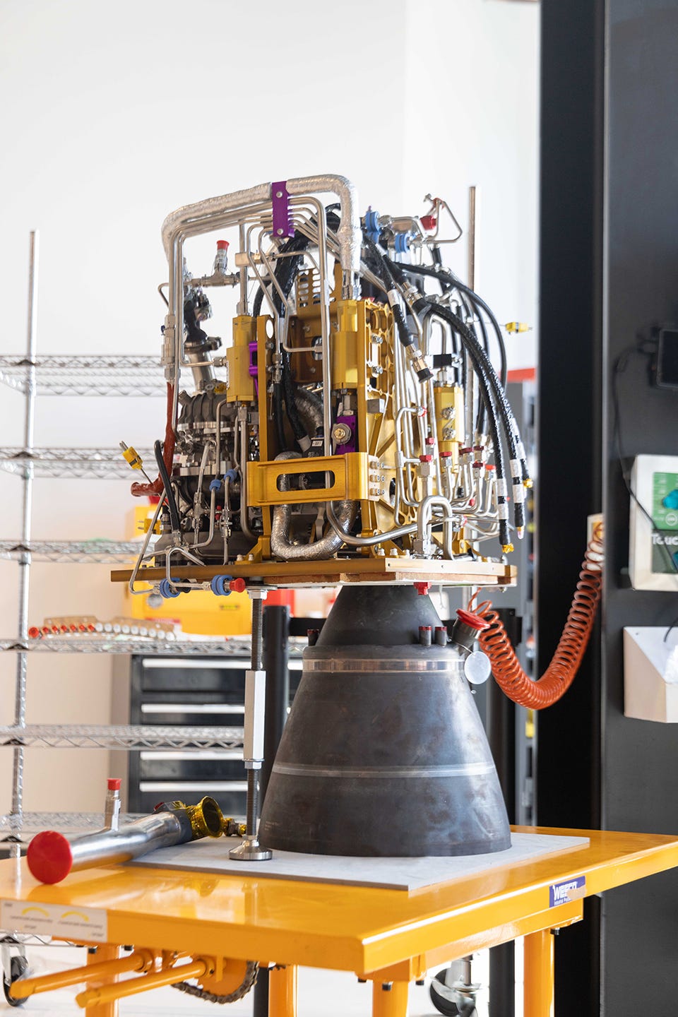
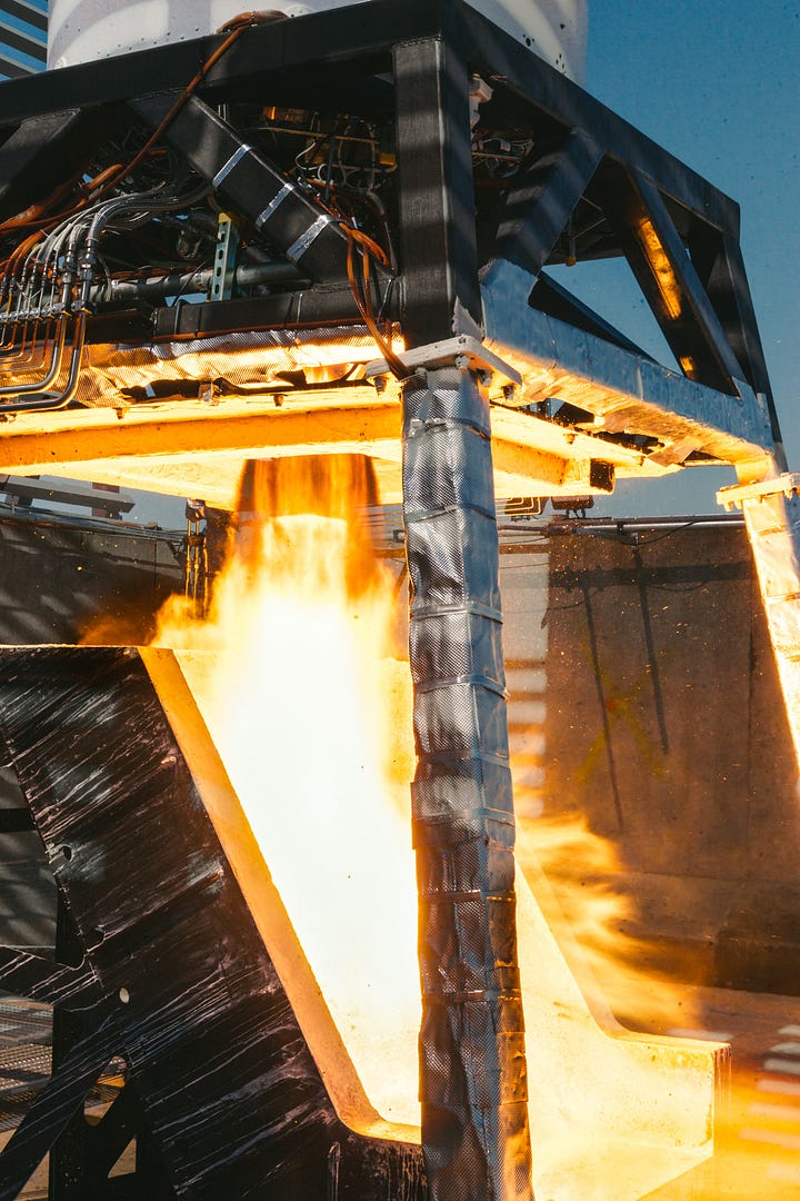
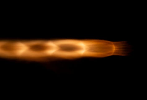
The E2 Engine is a simple, robust, resilient machine. It starts up. It burns smooth. It shuts down. It’s tolerant to a variety of startup sequences and inlet conditions. Recently, a qualification E2 engine achieved a 4x life on total duration and starts. After 28 starts and 1300 seconds of run time, this fleet leader shows no signs of performance degradation. E2 wants to run, and it wants to run for a long time.
It wasn’t always like this though; engine development is unforgiving. Thousands of decisions go into designing an engine, into architecting its sequences, and into building its test stands. When you go to start it up, they all need to be right. Otherwise, you’re likely to be exercising the test stand’s fire suppression system.
I started the ABL engine program from scratch. Over the years, we have burned through hot walls, hard started chambers, and fine-tuned our turbomachinery. Along the way, we put together an excellent team of engineers and technicians. We built test stands and then we ran those test stands hard. We accumulated hours and hours of hotfire time across fifty different engines.
We worked relentlessly to create a flight-worthy engine system and went from nothing to having ten flight-worthy engines tested and installed on a rocket in under four years. I’m excited to talk through the path we took to get there.
The E2 Engine
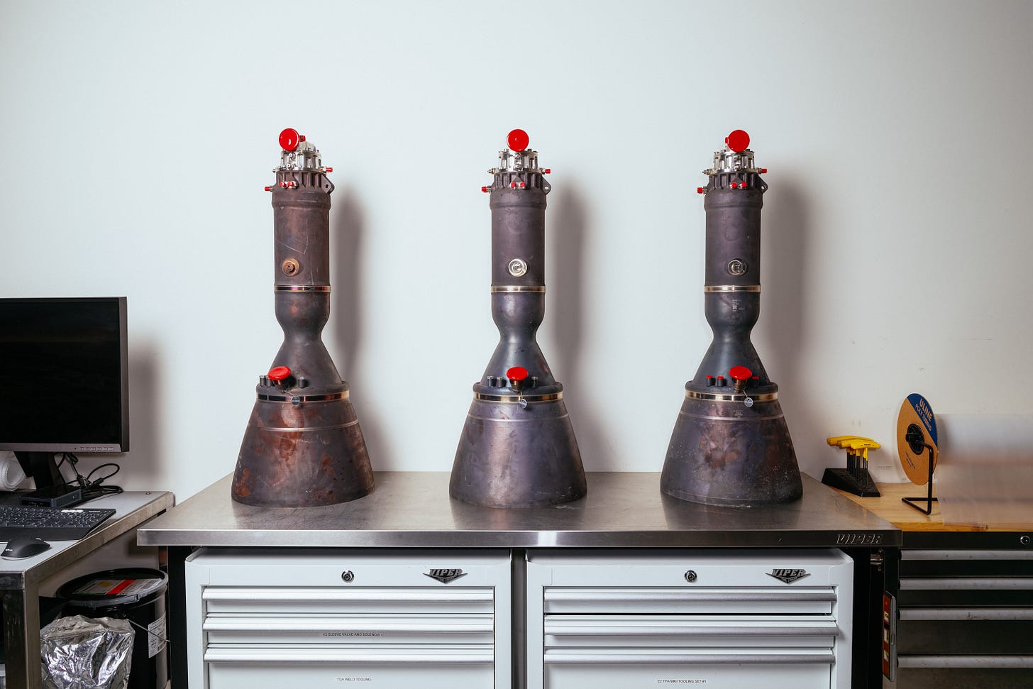
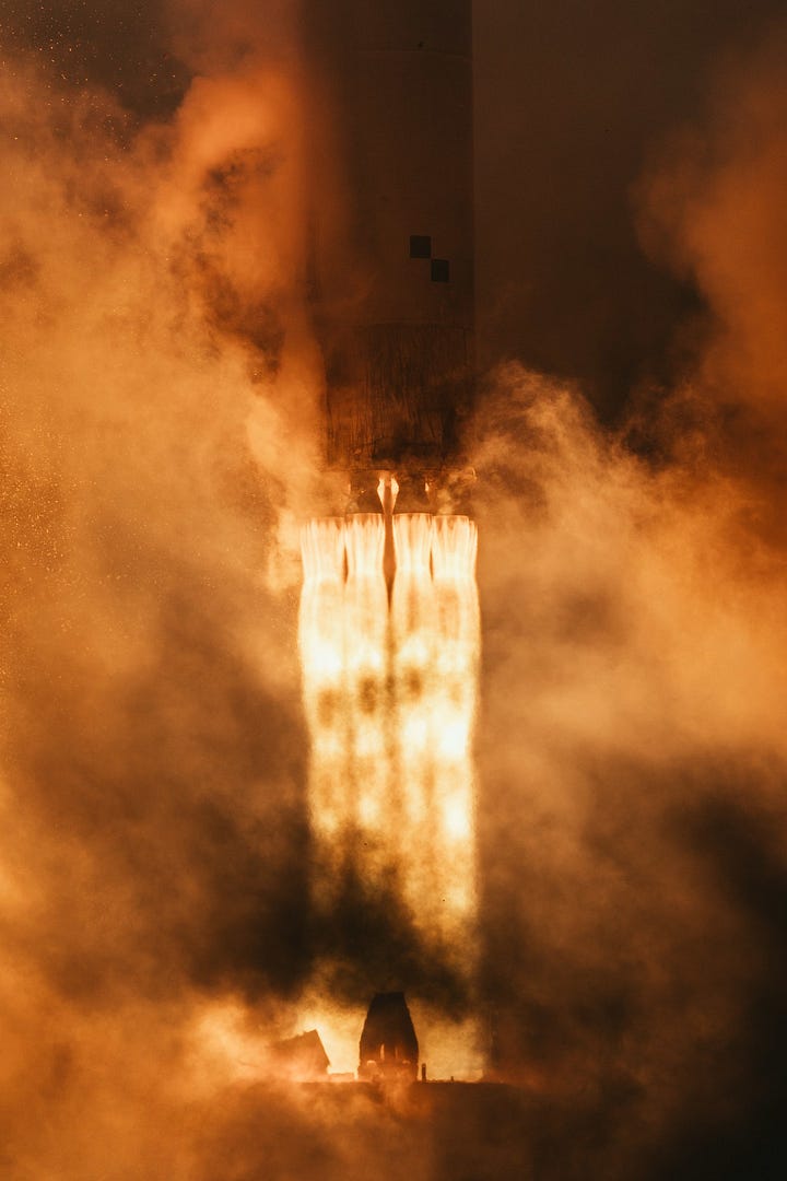
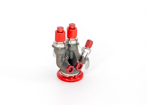
You don’t get to a simple, robust, resilient engine by accident. The E2 engine runs on Jet-A and Liquid Oxygen, the most commonly available propellants in the world. It operates on the robust Gas Generator Cycle, and is powered by a single-shaft turbopump. The RS1 rocket uses E2 in three variants. Stage 2 uses the E2 Vacuum engine. Stage 1 uses E2 Sea Level Radial and Center. Center is a tightly-packaged double chamber variant of Radial mounted at the center of RS1’s aft end. Each generating over 16,000 lbf of thrust in vacuum, these engines are designed, manufactured, and tested in-house at ABL.
My Background
You might call me an unlikely candidate to lead an engine program from scratch, but I was hired by ABL in 2018 to do just that. My background was in commercial aircraft interiors, web development, semiconductor fab fluid components, and SpaceX Falcon 9 hydraulic systems. Rather than direct propulsion experience, I leaned on lifelong curiosity, mechanical intuition, and engineering practical solutions to a wide range of problems.
In college I pursued the air and ground-based mechanical and aerospace engineering coursework, shunning classes on rocket engines and orbital mechanics. It wasn’t an exciting time for spaceflight. The Space Shuttle was heading towards retirement, and the remaining launch vehicles were primarily Russian and American rockets from the 1960s. Unless you were really paying attention, and I wasn’t, you knew nothing of the SpaceX Falcon 1 launches that were moving incrementally closer to orbit.
In 2015 SpaceX’s repeated attempts to land boosters finally did catch my attention, and I joined the Falcon 9 stage systems team alongside ABL founder Harry O’Hanley. I learned a lot about reusability and what it takes to land rockets on barges and on land. Unfortunately, I didn’t learn as much about engines. I was obviously aware of them and how they worked but didn’t spend much time in or around them. I recall a coworker talking about an engine performance-related question they had asked an interviewee, where they scoffed at the inadequate answer they received, and which I myself would not have been able to do better than.
All that is to say, I joined ABL as a blank slate. This meant two things: 1, I had to do a lot of research to figure out where to start. 2, I did not have any predispositions about designing an engine that could hold me back. I was a team of one and I hit the textbooks, NASA monographs, and research papers on rocket engines to start wrapping my head around the problem.
Design
NASA monographs, describing in detail the design problems central to rocket engines and their components and their solutions engineered in the 1960s, are available to the world at nasa.gov. Reading through these, you end up with thousands of tidbits, ranging through rules of thumb, key ratios, materials that don’t work well in engines, materials that usually work well in engines, and so on. What they lack is a single best set of solutions for the specific type of engine you want to build, test, and operate. This is where the fun starts.
Most rocket engine designs do not start with textbooks and monographs. They often have a starting point, whether it be a previous generation of engine within the same company, a legacy technology demonstrator that was crated up after completion awaiting a new owner, or key components or IP purchased from another entity.
At ABL we started from a true clean sheet. Some small components – seals, bearings, sensors – were purchased from vendors, but everything else was designed from scratch. And not only the engine itself, but the test infrastructure, the test software, and entire test sites we built from bare dirt. Since our trade space was completely open, we had to move quickly to make key early decisions to limit that space to avoid the paralysis that too many choices can induce. A few things seemed obvious when looking at industry examples and the high level understanding we had of engines and engine manufacturing technology.
First, engine cycle. All rocket engines combust propellants in a combustion chamber and accelerate the biproducts through a nozzle to generate thrust. The way the propellant gets to the combustion chamber is dictated by the type of engine cycle, each with its own advantages and disadvantages. These range from the pressure fed cycle, where the propellant tanks are held at a high pressure and propellant flows directly from them to the chamber, to the staged combustion cycle, where propellants flow through pumps and turbines and burn a bit of each along the way to self-power the pumps. We chose the gas generator cycle, which can provide moderate efficiency, and where each component can be tested and tuned on its own without requiring the others be present or even ready.
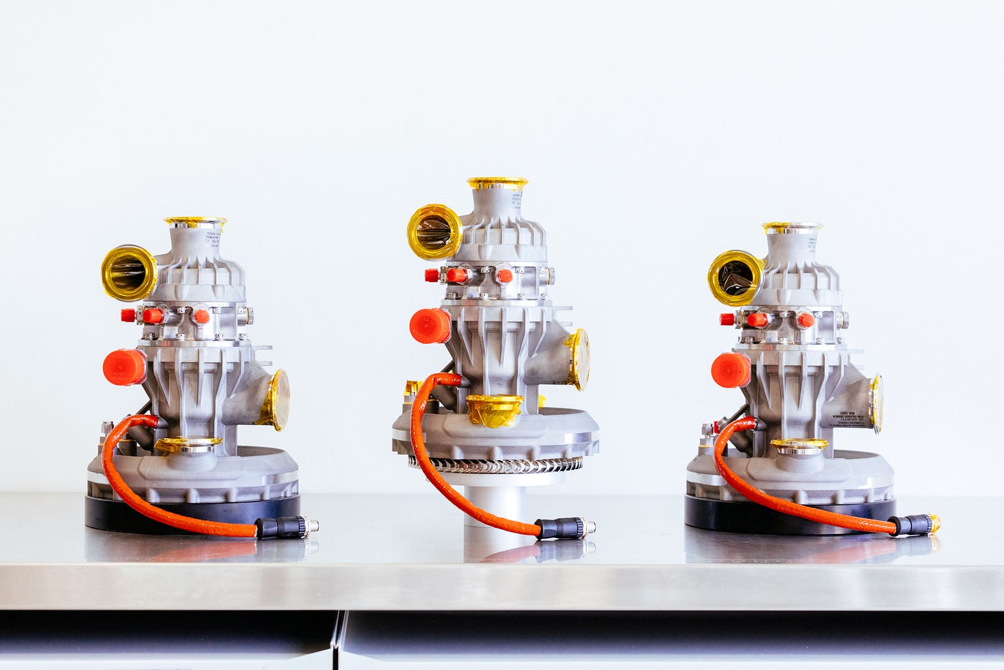
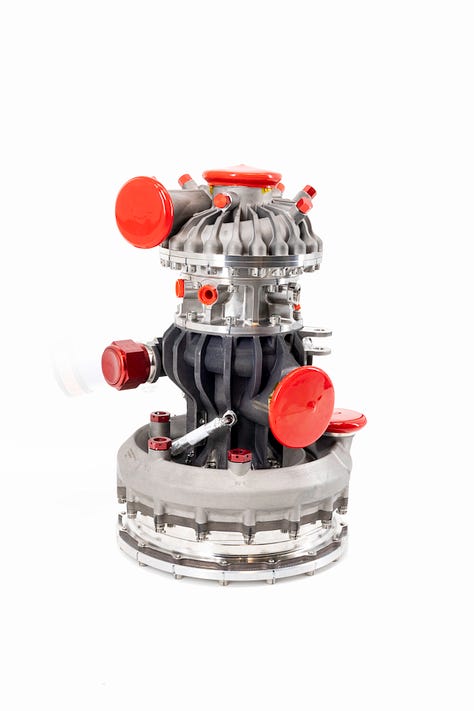
With the cycle chosen we split out the four key areas to work on: 1. The turbopump, which takes propellants stored in the rocket at low pressures and pumps them up to the high pressures required to feed the engine’s combustion chamber. 2. The main combustion chamber. 3. The main chamber injector, which mixes the propellants coming into the chamber just so to ensure they mix and burn steadily and efficiently. 4. The gas generator, a small combustion chamber that provides pressurized hot gas to power a turbine that powers the turbopump.

Before getting into any fine details, I gathered equations from textbooks and monographs into an excel spreadsheet that worked sequentially through sizing the requirements for each component. I later learned that this is called a “power balance” or “1D code” in industry. Basically, if you want X thrust, you must flow Y rate of propellants, and you must set the main combustion chamber exit to Z diameter. Parts of it were as simple as this, but when I added in the governing equations for turbopump impeller sizing it became fairly complicated. Time to get into detailed design.
To divide up the work, I took the turbopump and main injector, and the other two engineers on the team took the main combustion chamber and gas generator.
Turbopump
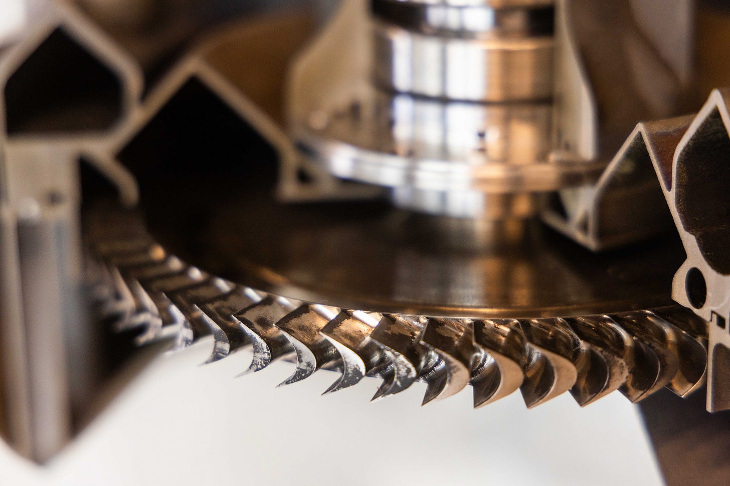
I dug in on the turbopump, a frightening device spinning at about 50,000 RPM and operating with a complex system of fluid passages and bearings and impellers and turbines. A typical turbopump boosts propellants from around 50 psi to 2000 psi, while pushing many gallons per second into the combustion chamber. By contrast, a Formula 1 race car fuel pump also pumps up 1000s of psi of pressure, but flows less than one gallon per minute. If you look at the cross section of a typical turbopump (for example, the F1 turbopump from the Apollo missions), you’ll see the expected impellers and turbines but will quickly get lost in a sea of complex secondary features such as slingers, balance pistons, labyrinth seals, recirculation channels, multi-stage turbines, bearing coolant systems, and so on. And even for the impellers and turbines, a 2D cross section highly simplifies them, as their sweeping, spiraling blades are one of the most 3D, organic looking features in a rocket engine.
I can’t go into the exact details of how our turbopump design shook out, but the general idea was to not add a feature until we were convinced it was needed. Keep it as simple as possible as long as possible.
The 1D excel code took impeller and turbine design as far as they could go on paper, spitting out speeds, inlet and outlet sizes and blade angles, and expected efficiencies. There is a big gap between the end of the equations and the gracefully shaped blades of final designs, which is spanned by specialized software.
While on the phone with an engineer who was demoing the software we ended up purchasing, I bluntly asked “if we have a set of inlet requirements and exit requirements for an impeller, why can’t the software just give us the best answer?” Using the software required a huge amount of tweaking of parameters and manually adjusting curves until things looked just so. He answered that you don’t know exactly how a design is going to perform until you do time-intensive computational fluid dynamics modelling, so you have to design and iterate based on your experience and intuition. Ultimately, impeller and turbine design is part equation, part rule of thumb, with a sprinkling of art. Wild, for something that I had previously perceived as a triumph of engineering.
Injector
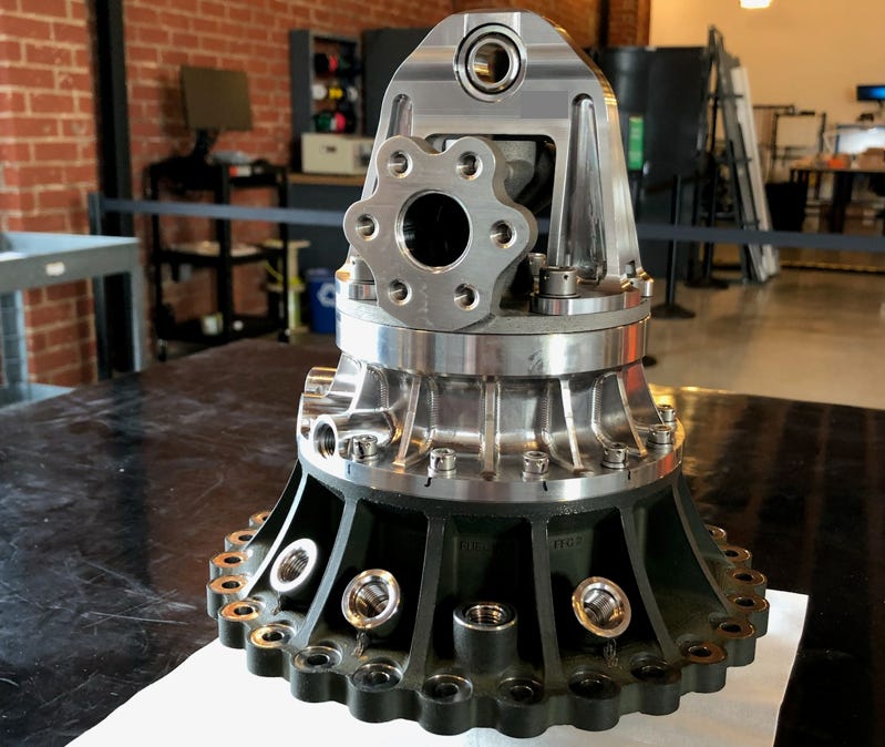
I interspersed pump design and part procurement with work on the injector for our main chamber. Since I had significant valve design experience, we decided to go with a pintle architecture. Most engine heritage uses showerhead or impinging jet type injectors, where an array of 100s of small holes in the injector spray propellants in a way that they collide with each other and atomize into small particles that burn quickly and efficiently. These designs, however, require a network of complex passages within the injector, and precisely controlled injection hole diameters, angles, and placements. This adds up to an expensive, manufacturing-intensive process, and as far as we could tell from the resources available then, 3D printing was not an appropriate solution to make it simpler, as it could not provide the precise dimensions and surface finishes required. Pintles require none of this – they inject propellants in two “sheets,” one axial, one radial, that collide with each other to provide the atomization needed for good combustion and are designed and manufactured much more like valves than not. It also allowed us to simplify packaging and reducing the total number of parts we had to work with.
Main Chamber
Main chamber design was another interesting exercise in theory meets reality. We narrowed our design trade space quickly by deciding we would 3D print our chamber and would do so using machines and materials that were well-distributed and understood – nothing cutting edge. This set the maximum size for our printed parts, and set our material as Inconel. Inconel is a nickel superalloy initially developed for use in jet engines. It is very strong, very heat tolerant, very weldable, and was readily available in 3D printers around the country. It is also difficult to machine and has poor thermal conductivity, two challenges we had to take on and live with.
The crux of rocket engine combustion chambers is that the combustion inside them reaches about 6,000°F (flirting with the surface of the sun at 10,000°F), and even the best metals get quite soft at 1,200°F and melt at 2,500°F. There are a few ways to make a chamber survive this, but the most common is to run a portion of the propellants through the walls of the chamber to cool it. This sets up an interesting thermal management problem. You have to make the inner wall of the chamber as thin as possible to ensure the cooling effects of the flowing propellant can penetrate it, but not so thin that it ruptures under pressure. You have to make cooling channels in the wall narrow so the propellant flows at high velocity and cools the wall more effectively, but not so narrow that they generate excessive backpressure in the system that requires a huge amount of effort from the turbopump to overcome. You have to let the propellant suck as much heat out of the wall as possible, but not so much that it boils or breaks down.
The combustion chamber engineer wrote a slick code that could optimize all of these parameters in a continuous sweep down the length of the combustion chamber, spitting out geometry that he could directly port over to 3D modeling software that would in turn feed the 3D printers. We made a few key assumptions and locked down a design so we could get into test and adjust, if needed. Five years later, we continue to be pleased with the outcome of this sizing. To this day we have not changed from that original chamber cooling solution. The design just works.
Build the Hardware
One of the most energizing moments during a product development cycle is when the parts you have been designing on a computer screen for months finally show up in person. There’s a general rule for when you first see your parts – they are either larger or smaller than you were picturing them, never exactly how you imagined. Most of our early parts were printed and machined by aerospace manufacturing shops from around the country. These shops are a special type, taking on high-value, low-quantity jobs, and delivering them rapidly to support the pace required by the industry. We had a handful of key partnerships and owe a lot to them. Seeing our early engine parts in person was awesome. First a small print of a chamber section to prove out thickness limits, then a GG, then chamber sections and injector parts. It was feeling very real.
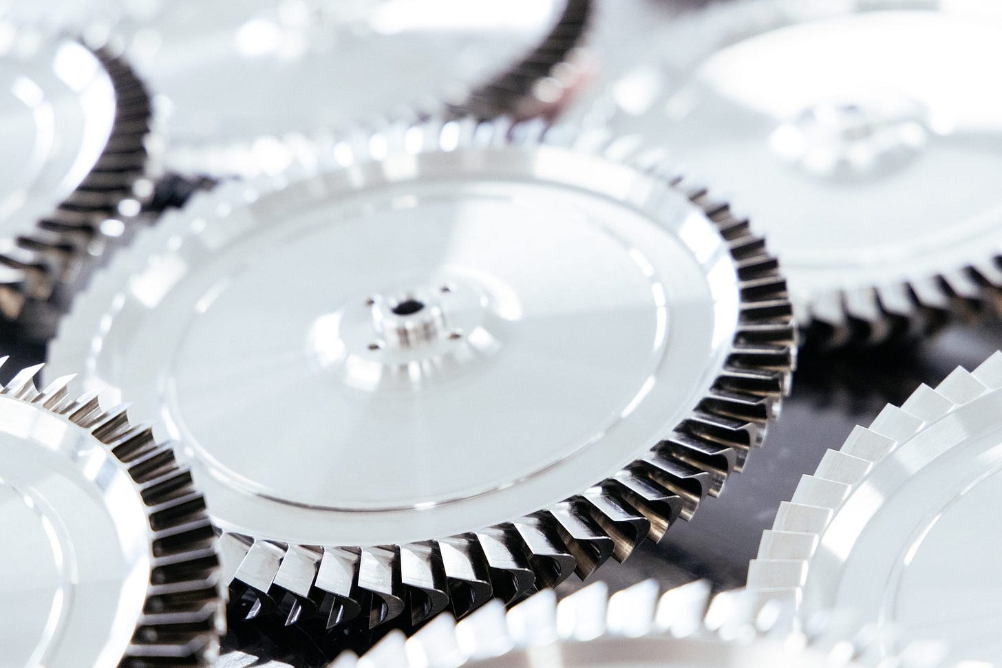
An outlier was the impellers and turbine for our pump. I knew they would not be the kind of parts just any machine shop would take on, and dug around and found a few that specialized in making them. When I received quotes back, it was wake up time. The impellers and the turbine were each quoted at around $18k – more than a small car! Even worse, the lead time was four months. While the cost was high, the lead time is what was ultimately untenable. We were certain to have to go through a few revisions to these designs before they were ready to fly, and adding a four month cycle to each of those revisions would drag out the overall pump development time beyond what was reasonable for a startup trying to move quickly and prove itself.
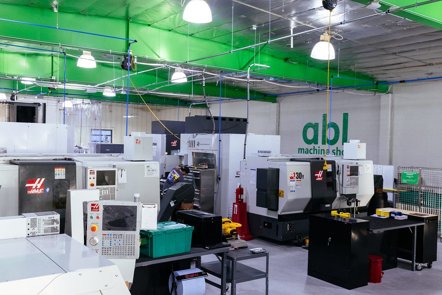
It was time to verticalize. We leased our first 5-axis mill and hired a machinist. These parts were made from hard metals and had small intricate features. The machining wasn’t easy. I think we spent more than the outsourced quotes in broken end mills on the first set. But over time we got better, due to advances in our machining and advances in the design.
At one point, I received a well-deserved earful from our machinist about how tightly spaced the turbine blades were. The program was taking nearly a month to run and required tiny end mills that broke often. We performed a turbine blade count study to see if we could use fewer blades with more space between them. It turned out the performance impact of running fewer blades was minimal, so we cut the number down, allowing our machinist to use larger, less fragile tools. Machine time dropped to less than a day, which was a significant win for turbine cost and machine time. It was also a good lesson in thinking comprehensively about a design’s manufacturability (those passages between the blades looked so big on the computer screen!) in addition to its performance.
We can now produce impellers and turbines in a matter of days and at a fraction of the cost. There’s an example of the benefit of this that we reference often in tours and when recruiting engineers to our propulsion team. At one point during early pump testing, we kept running into performance issues with our fuel impeller. It wasn’t grabbing the incoming flow effectively and was giving our engine unpredictable performance. While we could combat this and work with it on the test stand, we ultimately concluded that it wasn’t going to work for flight. From the point of making that conclusion, through redesigning the impeller, getting it into the machine shop, getting it built into a pump and balanced (a step in every pump build to ensure everything spins smoothly), and getting the pump back into test to prove out the design change, it took us 10 days. If we had not brought that capability in house, we would have been stuck with either a multi month delay or with transferring the impact of this performance issue into other rocket systems or into the performance of the rocket itself. Big win.
We’ve continued to verticalize where it has made sense. We now operate a handful of 3D printers in house, have numerous 5 axis mills and multi-axis lathes. Our turbopump rotors are balanced in house. Many of these processes or technologies seemed daunting when we first learned of them or saw them performed by another party. But once in house, you learn, you do it over and over, and it becomes routine. During my time at SpaceX we saw landing rockets go from insane to routine. The same has happened here at ABL, first for building engines and then for testing them.
Build the Team
Building an effective team is often more challenging than building a working engine. We’ve strived to stay as small as possible as long as possible, being very thoughtful about who we bring onboard and when. Part of ABL’s philosophy is to produce more than we consume. As we strive to do more with less, we’ve often found less enables us to do more.
We started the propulsion program in 2018 with two engineers (myself included). We were a team of five for the first two years of development - all the way through running our first fully integrated engine. Today, it’s a team of fifteen. We’ve made hires that worked and ones that didn’t. We’ve made new grad hires and experienced hires, from inside the industry and outside. We’ve found a few traits to be key indicators of success, which are influenced by our simple engine architecture that allows first principles to prevail:
Engineers who don’t stay behind a desk all day, who love getting their hands on hardware, being in the field, helping with tests are almost always more effective than those who do not.
Where engineers bring experience, they don’t over-focus on it. They allow their experience to be a guide, a part of the puzzle, not the whole answer.
An engineer may own a few specific parts of an engine, of the rocket. They will be most successful if they have a comprehensive understanding and interest in how those parts fit into the bigger picture. How they effect the teams interfacing with them, the build, operation, and performance of the rocket.
The best engineers never sit on what they think is right, they quickly take action or they speak up regardless of org structure or seniority.
Overall, the best indicator of success is a strong foundation of mechanical and fluid dynamic intuition. From there, it’s easy to fill in the gaps.
We expect a lot of each engineer and they all work incredibly hard. And because the team is small, we give each the opportunity to experience real ownership of a large part of the design, build, and test of rocket engines.
Test and Iterate
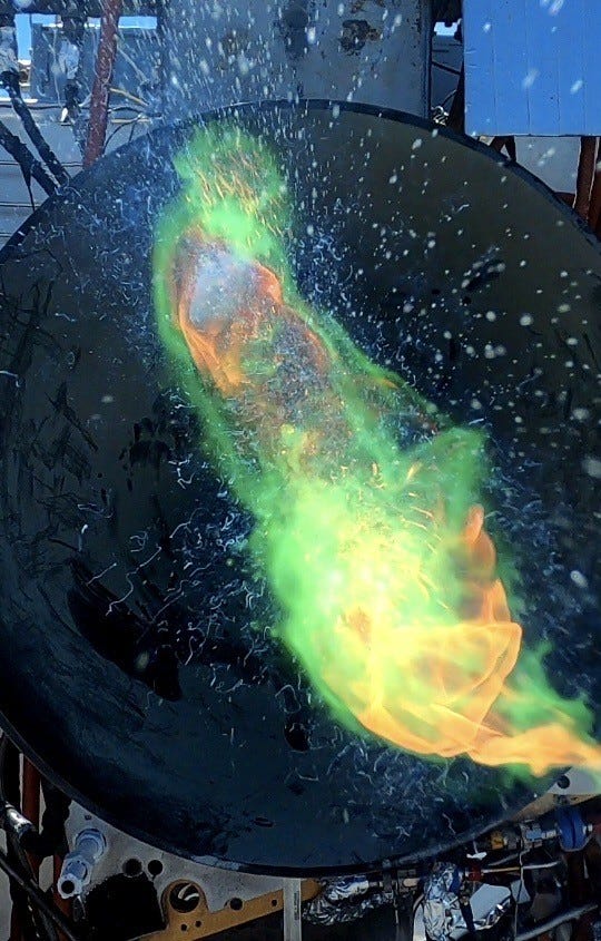
We started our first E2 test campaign in summer 2019, a just under a year after we started engine design. Our first test site was on a flat concrete pad at Spaceport America in New Mexico. There we set up our first test stand which took us through pressure-fed (no turbopump, yet) testing of first our GG and then our thrust chamber. In this test campaign we accomplished a few things and learned a few things. We deployed to an austere location, we ran our first combustors, we lit with TEA-TEB (the pyrophoric liquid that is used to start many rocket and jet engines), and we worked with cryogens. We learned that snap rings don’t work well inside of combustion chambers and we learned that pintles melted easily and weren’t the slam dunk we thought they would be.
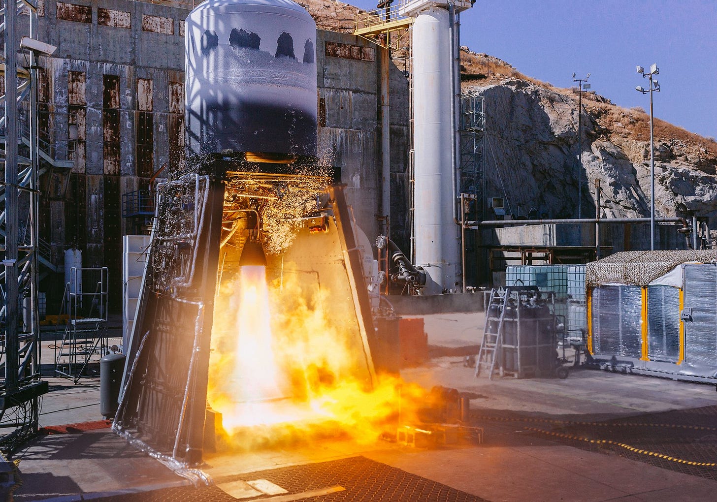
In 2020 we deployed to site 1-56 at the Air Force Research Laboratory (AFRL) near Edwards Air Force Base, where we again set up our pressure fed test stand but also a development rocket tank for pump-fed testing. Having the opportunity to operate at this site significantly accelerated our development program. At AFRL we ran our first turbopump, and it pumped! We had some challenges. We melted turbines and we had power instabilities, but we learned and adapted. Changes were made to the test stand to make the engine more controllable, changes were made to the turbine exhaust to make it more stable, and changes were made to the turbopump to make it more efficient.
In the time between the testing at Spaceport America and AFRL we designed and manufactured a new version of our injector that didn’t use a pintle. Since we had shown we could make a chamber that worked and a GG that worked we were no longer as concerned about other injector types, and took a leap on a manufacturing method that was much less arduous than the traditional method. It wasn’t that we didn’t think we could make the pintle work eventually – I’m confident we could have – it was that we knew this other type of injector was almost certain to work right away. And it did. And we have not changed it since.
One of the biggest accomplishments at AFRL was running a fully integrated engine, which we did on our Stage 2 development tank. We had a fully integrated engine, with a pump, GG, and TCA closing the loop and running under their own power. We were in the game.
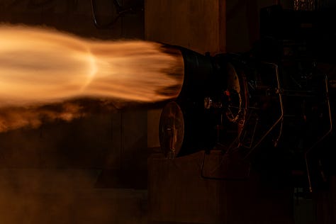
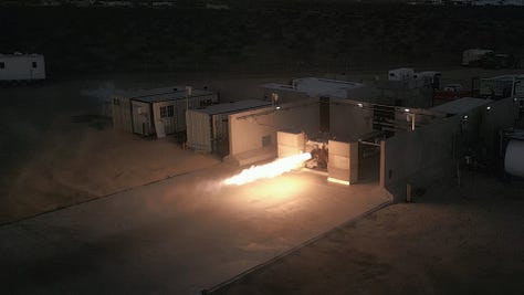
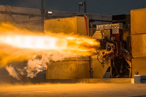
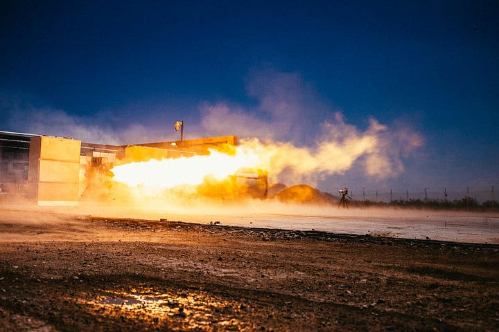
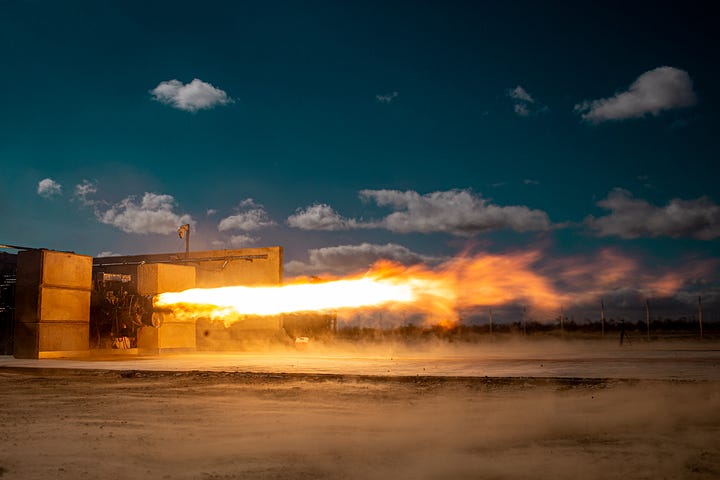
2021 was dedicated to building out a brand new test site in Mojave, CA and getting into testing there. As we did, we implemented a new round of upgrades to the turbopump and matured the design of everything around it on the rocket. At the end of 2021 we started the testing of engines for Flight 1, a campaign that looked dramatically different for us. We had multiple test stands, we were running many, many engines, and we were running them for full flight durations. All of a sudden our total engine run time was measured in thousands of seconds rather than tens of seconds. And they were working.
In 2022 we made thrust upgrades to the engine to give us more power. We also kicked off the build of a new engine test site, dedicated for production testing. We would soon have the ability to run engine development and production test campaigns entirely in parallel. In 2023 we repackaged the same engine components into a configuration that was more modular, making it even easier to build and test. More recently, we’ve optimized different key features of the engine, such as the TEA-TEB system to enhance reliability and long term performance.


Looking Forward
We’ve built 50 individual engines and operated them on 6 different test stands across 3 sites. These units have racked up many hours of hotfire time and hundreds of starts. E2 iterative development is not complete, and it may never be. There will always be small improvements to manufacturing, performance, mass, or cost to make.
We’ve learned a ton and will continue to do so. Problems that seemed like existential crises at the moment look small in retrospect. You assess, you solve, you move on, you don’t make the same mistake again. We’ve had print powder in pump bearings, underperforming volutes, underperforming impellers, melting liners, melting turbines, melting manifolds, melting tubes, chugging pumps, unstable gas generators, countless leaking seals and hard starts. Each solved problem makes our engineers stronger, makes our engine stronger, makes our company stronger.
You can only learn and solve problems like these when you test. Our biggest misses have come from not continuing to test when we didn’t absolutely have to, and pushed uncovering issues until further down the line where they were more impactful. Just like when running up a hill in a race, don’t stop and rest when you get to the top, keep the pedal down and get over the crest.
Looking forward, we are continuing to build out our team with a blend of talented generalist engineers and propulsion engineers. It is awesome to see the assumptions and institutional knowledge we have built up over the last 6 years both leveraged and challenged. So far the results have been great, and I am excited to be a part of it.


